Basement/Substructure Waterproofing Solutions
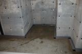
![]() Today there is an ever increasing demand for using every available usable space within your home; this demand has created the extensive surge for the conversion of existing cellars/basements. We can transform existing unused cellars/basements to dry habitable areas with the Waterproofing Solution (tanking system) complying with the British Standard BS 8102 “Code of Practice for Protection of Below Ground Structures against Water from the Ground”
Today there is an ever increasing demand for using every available usable space within your home; this demand has created the extensive surge for the conversion of existing cellars/basements. We can transform existing unused cellars/basements to dry habitable areas with the Waterproofing Solution (tanking system) complying with the British Standard BS 8102 “Code of Practice for Protection of Below Ground Structures against Water from the Ground”
Commercial Projects
 Whether you are a business looking for a dry storage environment or a design professional with a structural waterproofing problem we can help. We work on commercial projects involving structural waterproofing design, remedial waterproofing design and structural waterproofing installations or repairs.
For professionals involved in the design chain we also offer specialist consultancy on waterproofing projects and structural waterproofing design failures.
Project Steps
First contact – First of all we will discuss your project over the phone and get a feel for your requirements, budgets and time-scales. We can offer some basic advice on options and usually suggest indicative costs for your project.
Site visit – Once we know roughly what you need we will visit your property, discuss your requirements in depth, review any plans and carry out a budgetary survey.
Quotation – Following our visit we will usually work out a quotation for your project within one week.
Detailed Specification (Major Works) – If the cost and product is to your requirements we arrange a detailed survey and prepare a specification. We may need to undertake trial holes and start the structural design process if your project involves significant structural works.
![]() Design review and budget adjustments – Once the drawings and specification are ready we sit down with you to firm up the detail of the project and make any last minute adjustments.
Design review and budget adjustments – Once the drawings and specification are ready we sit down with you to firm up the detail of the project and make any last minute adjustments.
Contract & Start on Site – As soon as the planning phase is finished its full steam ahead with your project and you’re on the way to having a beautiful basement!!
Drainage Options for Basement Waterproofing
Sumps & Pumps
When specifying a sealed cavity membrane system, full consideration must be given to drainage, when installed below ground.
 The concept of the drained cavity system is to collect and mange any moisture which breaches the iSump and pump systemntegrity of the structure by channelling, collecting, and discharging such free water via a suitable evacuation point.
Channels, laid to a nominal fall, can discharge passively into a sump or be connected to a drainage system but access for maintenance should be provided.
Access ports/jetting eyes allow inspection and water jetting of channels, while sumps have a sealed access cover which allows for annual maintenance checks to be carried out, which are recommended. If drainage has been installed, it should be flood tested before covering it up to make sure the system works.
As pumps require servicing to maintain maximum efficiency, we provide a 10 point “Clean & Check” service which is to be undertaken annually, all our customers are contacted when this service is required, therefore providing peace of mind.
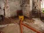
Perimeter Drainage Pipe System
 Perimeter drainage pipe system positioned at the crucial floor wall position The perimeter drainage pipe acts as a perimeter conduit bedded in at the floor/wall section. Where appropriate, it can be laid under the concrete base slab to take ground water to a sump or soak away, and reduce floatation pressures from bearing on the concrete slab. It is fully perforated for maximum performance, and incorporates an outer geotextile filter to prevent particles from entering the pipe.
Floor Wall Joint Channel Drainage
Jetting eyes can be fitted to into the perimeter drainage system to enable the channel to be cleaned out periodically if necessary.
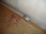
The floor wall joint channel is a PVC drainage conduit designed for the control of water ingress in below ground situations. It is fitted at the periphery of the floor at the vulnerable floor/wall junction. Holes in the channel wall allow water to ingress at this point to drain away to a sump chamber or soak away. Access ports are available to allow maintenance and inspection.
Central Room Drainage System
Should it not be possible to install the floor wall joint drainage channel system, for structural reasons for example, the Central Room Drainage System can be installed, this consists of strategically placed drainage outlets and feed pipes laid within chases formed within the basement floor oversites.
The termination of the feed pipes is usually into a pre-formed sump chamber containing an automatic submersible pump to discharge any ingressed ground water to a suitable drainage outlet.
Over the central room drainage system a concrete base slab is laid ensuring that any potential surface water is directed to the drainage outlets, a controlled flood test is undertaken (prior to installing the cavity drain tanking floor membrane) to confirm that no ponding occurs and that the water reached the sump chamber.
Free Lime Risk
When new concrete forms the structure, to walls or particularly floors, there is a risk of excess free lime leaching out during the curing process. When a cavity drain system is used in this type of application, a silicification pre-treatment of the concrete should be used to prevent the risk of free lime build up, and a potential reduction in water flow. Keisol is applied as two spray coats for this purpose, and is available in 30kg drums.
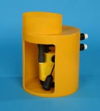
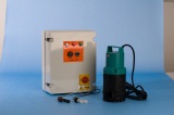
Submersible Sump Pumps

In a basement installation the design and requirements would be This pump is positioned within the sump chamber and is controlled by an automatic integral float switch. As the water level increases within the sump the integral float rises and when the pre-switch level is reached the pump will automatically operate and discharge the water. bespoke to each dwelling, however a standard dual sump chamber would contain two AMA 302 SE/HP pumps, with float switches set at different levels to act as duty assist or duty standby. This system can also collect grey water from sinks, showers, washing machines and dishwashers.
Pumping stations can also be installed to deal with foul and/or surface water.
Power Failure
If you have installed a cavity drain system internally, one of the main design considerations is how are you going to manage the water collection and discharge. This can be done passively into existing drainage points, if available and appropriate.
However, the majority of projects require a collection sump + pump, to automatically manage the evacuation of any water ingress. This type of unit requires mains power to operate, so what can be done if the power fails, and is coincident with high water ingress? Please read on.
High Level Alarms
An audible high level alarm to warn of mains power or pump failure within These High Level alarms can be fitted in to the sump system so if there is a pump failure then the alarm will sound to issue a warning to the property owner, who can take the action required to prevent any internal flooding.he pumping station/sump chamber.
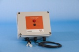
The alarm is normally powered by 240v mains voltage, however in the event of mains failure the unit automatically switches to the battery back-up situated within the unit. The 12v battery, which is continually trickle charged is built into the control panel circuit and is designed to last for life.
The system operates via a float switch fitted within the chamber, normally fastened to the pump handle, and is connected to the control panel that is normally situated within 8 metres of the pump chamber in a dry environment.
The alarm is also fitted with a ‘test’ switch to allow routine checking of the Alarm Battery Backup system without the need to enter the sump.
 A special option is also available with volt free contacts so the unit can be wired to give a remove signal ie building management system or spate audible / visual alarm.